I've really enjoyed the "revamped" web pages -- and at the risk of overkill, offer some more input that might (or might not -- strictly your discretion!!) be of use in connection with the "Gadgets" page.
Click pictures to enlarge, then use your "Back" button to return.
 Photo #1: Photo #1:
This item tracks with a recent request for "headliner" ideas from one of the members. On our 1976 I-36, the forward cabin "hatch" was framed (on the inside) with vinal lining which was internally stapled (unfortunately, with steel -- not monel, or stainless!). Before installation of a roller furling jib the hatch was frequently used to "stuff' sail bags "down", and for "racing types" to exit from below. Needless to say, the wear and tear of 20 years of such usage played havoc with the lining. While replacement linings are available (I'm told), we opted for a "teak" framing (1/2 inch rounded). Cost of materials was roughly $25, including "plugs"/varnish etc. Labor time was roughly 8 hours.
|
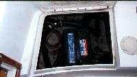 Photo #2: Photo #2:
Our 1976 I-36 came with two batteries -- both used in a house mode, but also to fire up the old Perkins!. As we've ventured into more offshore usage, and as a general safety measure, we decided that it would make sense to install a third battery dedicated to "engine" usage, if and when needed. The issue: Where to install the third battery. We opted for the aft/starboard lazarette. Installation was simple. Involved "manufacturing" a box out of 3/4 inch marine plywood to fit the battery -- which was then secured to the existing infrastructure (in our case, a steering quadrant support) with a six inch stainless steel strap. Ultimately, the plan is to connect the "emergency starter" battery into our charging system -- but, as a short term expedient, we simply keep it charged using a separate (auto type) trickle charger unit (once every 4-6 weeks, for 24 hours seems to work well), supplemented by a 12 ft. auto "jumper" cable, to be used in the event of house battery failure.
|
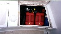 Photo #3: Photo #3:
The aft lazarette has, historically, been a place to dump extra life jackets, other junk -- all of which suffers from the elements in less than a year. Our solution was to create an approx. 2 ft x l-1/2ft "box", again of 3/4 inch marine ply, which nicely accommodates two 2-1/2 gallon plastic (Costco) diesel fuel cans, which we use for reserve capacity on extended cruises. It also provides some convenient niches to store (upright) the fuel "bug" stuff and a gallon of engine oil.
|
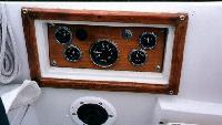 Photo #4: Photo #4:
Not sure that other's have had this problem, but our instrument panel -- after 20 years -- was a total "mess". Unlike some of the later models, our only shelter from the elements was a canvas cover, which was not always faithfully committed after a great day of sailing on the Bay. As shown in the photo, we finally "bit the bullet" and "manufactured" a new panel out of 1/2 inch teak and replaced all of the gauges, which were more than a bit shop worn! The gauge replacements were triggered by the need for a new tack, which is the most expensive of the cluster. Incidentally, West Marine doesn't stock the original gauges (Steward Warner). Our source was Mercury Marine, in San Rafael.
|
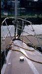 Photo #5: Photo #5:
Again -- this may not be relevant to many members. Our I-36 lacked a forward anchor "well" -- common on later models, at least those after 1978. Hence, anchoring for us was always a pain in the *!?^&---- or something to avoid. Our "old" way was to store the anchor in the aft/starboard lazarette. When needed, three folks would truck forward (one with the rode, one with the chain, one with the anchor). To address this "inconvenience", we installed an anchor roller (West Marine), drilled the deck for chain access (hawser hole and installed a simple "catch" basket in the compartment immediately forward of the "V" berth (so-called "rope" locker). Our configuration involves a 24 lb. Danforth, 60 ft of 5/8 inch chain and 200 plus ft of rode shackled
to the underside of the hawse cover which creates quite a tight cover
situation to keep water out when the bow dips under. Takes two hands to lift it up! Not ideal (vs. windlass), but certainly beats trudging anchor et. al. from cockpit to the bow! -- We think, -- since it hasn't been fully tested yet.
|
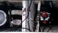 Photo #6: Photo #6:
And finally (I'm out of film!), some of the member's may have the bilge problem we've experienced. About 5 years ago we replaced the "primary" pump with a 2000 gph West Marine unit, with an auto float. Unfortunately, the size of the unit and other factors resulted in some 6-8 inches of water below the pump point --which, given the line fill, translates into something like 10 gallons or so of bilge water (fed by the ice box, shower, water tank overflow and stuffing box). To minimize this problem, we recently installed a 500 gph Rule pump, with an automatic start (internal to the unit, and turns on every 2-1/2 minutes" to monitor water level). The Rule was attached to the aft bilge bulkhead and effectively takes care of another 6 inches or so of water that is beyond the reach of the primary pump. Cost, including hose, wire, clarnps etc., is under $100. Having spent lots of $ on bottom blister's, I'm perhaps overly cautious about bilge water in fiberglass boats. A good reference on this subject, including the installation of a secondary pump, is Don Casey's book, "This Old Boat". We basically followed his suggestions.
|
In June 1999, Photo #5 above
described modifications to simplify anchor handling on pre-1978 Islander's
(those without bow anchor locker's). At that time the "below deck"
collection point for our chain and rode was a simple "catch" bucket below the
hawser hole.
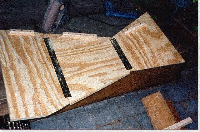
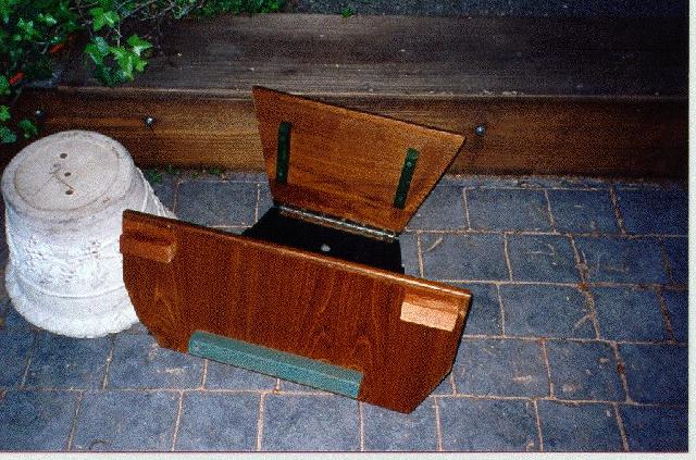
Latest"enhancement" - we've replaced the "catch" basket with a more permanent (but still removable) "platform" made of 3/4" plywood, faced (on visible sides) with 1/4" teak plywood and "hinged" with 2 piano hinges; the hinges simplify initial installation (via "bow" bulkhead opening) and allows for
easy access to below deck bow cleat nuts, bow light wiring etc. (i.e., just
"fold it up")
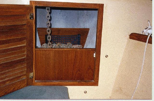
The 3 pictures above show the construction "build-up" and a post
installation view. Unit is secured to bulkhead with 4 screw bolts using
wingnuts to permit quick removal if needed.
We used 3/4 inch marine plywood as the "under-structure". This was
"sized" using a template made from cardboard, which I "hinged" using duck
tape. The plywood was sealed with Smith's clear 2-part epoxy. No stain was
used. What you see on the aft-facing side of the forward end of the bin is
1/4 inch teak plywood, which is glued to the 3/4 inch background plywood.
Same applies to what you see at the V berth bulkhead (i.e., 1/4 inch teak ply
-- which is topped with a teak strip routered to an "L" shape (also topped
the aft-facing side similarly).
I sprayed the "bottom piece" and the non-facing sides of the 3/4 inch ply in black. Not shown in the 1st picture are roughly a dozen 1 inch drain holes drilled into the bottom.
The aft end piece bolted with the four bolts to the bulkhead is actually
"set back" from the bulkhead two inches for air circulation (and,
practically, because of interferance caused by holding tank/water tank
piping on the forward side of the bulkhead). In other words, the 4 bolts
securing the unit are a good 4 inches in length. The four bolts do not
provide the entire support for the weight of the rope and chain.
"Underneath" the floor, at roughy mid point, is a structural support
(removable -- with a pin lock) that extends to the bottom of the bilge/hull.
Given current and prospective usage of the boat I don't envision any
"pounding" problems (at least haven't heard any shifting around in recent 25
knot blows on the Bay). If we were doing a lot of coastal cruising, problably
would revisit this to insulate the chain/rode from the port/starboard sides to minimize any wear on the hull at the contact point.
I left the wood strips (cleats), which are glued and screwed to the 3/4 ply,
for this eventuality (more comment on this below)
At the forward end -- the 3/4 inch edges (plus the 1/4
teak facing) rest against the hull -- with furniture stool type "rubber feet"
providing insulation from the hull. Originally I had planned to "box" the
sides (hence the wood strips/cleats that you see in the pictures) -- but I
decided that this wasn't necessary, at least currently. Most of the chain
weight, due to where the hawse is positioned, is near the aft-end of the
locker, with the major support provided by the bulkhead bolts and by the 2
inch "cleat" supports from the bulkhead. In the event of a "knockdown" I'll
have bigger problems...
The "mesh" visible on the forward end in the finished picture is West Marine sourced 3/8-1/2 inch "locker" base -- sort of a "rubberized" product with lots of holes. (The first picture only shows one cleat -- we installed the other side later, with as noted earlier, the original intention being to add "sides" to the unit ), Also, as noted elsewhere here -- bottom was drilled for drainage, and the
rubbberized base just provided a bit more elevation which I thought might
help with the drainage. Also sort of looks "nice".... No other real
rationale.
While the hinges allowed for easy installation of the pre-assembled
unit into the relatively small locker door --- they also permit easy access
to the underlying hull area, which came in handy last week when in removing
the forward cleats for topside varnishing several washer's got away from
us.....
Finally -- "why do it"?? First, without some organizational
structure, I find that the chain and the rode become something of a nightmare
to deal with. It was also a mess "upfront", so after removing the chain
et.al, took the opportunity to refinish the inside of the hull -- fresh
enamel etc. But more significantly, it was fun to "work out and do "-- and
as they say, "there is nothing half so much worth doing as simply messing
about in boats." I didn't keep track of the cost -- but under $100
including the Teak cosmetics. Construction time was an hour here/hour there
over several months.
---Still on the drawing board -- as a related "future project" is a
removable teak "connector" running from the hawse hole (which it would
circle) to the bow roller, to minimize deck damage as the chain is dragged
some 4 feet across the fiberglass (I currently cushion with a rubber pad --
but doesn't look very ship-shape). Concept envisions 4-5 inch wide1/2-3/4
thick wood, "drilled" for the hawse hold, and curved for the bow connect,
with a 3/4 inch center routing to allow for the chain flow. Do we really
need this?? No, but what else does one do during the winter months and wee
hours of the morning and night???
|
Hope this is of some use in connection with the I-36 web effort. Please pass on to whoever is the appropriate party.
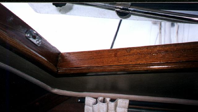 Photo #1:
 Photo #2:
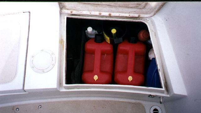 Photo #3:
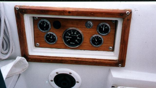 Photo #4:
 Photo #5:
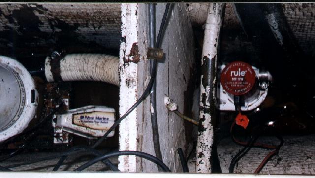 Photo #6: